基于Ipsec+GRE的BGP联合组网实现
IPsec VPN用于在两个端点之间提供安全的ip通信,但只能加密并传播单播数据,无法加密和传输语音、视频、动态路由协议等组播数据流量;
通用路由封装协议GRE(Generic Routing Encapsulation)提供了将一种协议的报文封装在另一种协议报文中的机制,是一种隧道封装技术,GRE可以封装组播数据,并可以和IPsec结合使用,从而保证语音、视频等组播业务的安全。
这里,我们采用Ipsec封装GRE的方式,进行BGP的组网实验;
1.Transit网络拓扑如下图所示
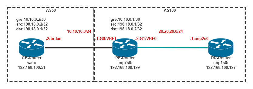
拓扑:
CE和PE通过10.10.10.0/24网段进行公网通信;CE上的路由信息同PE上的fib table 1进行通信,IP地址范围是10.10.10.0/24;
然后建立PE(Provider)和CE(Client)之间的ipsec+gre网络连接,采用ipsec over gre的overlay技术方案。CE和PE的gre 接口ip分别是10.10.0.2/32和10.10.0.1/30。192.18.0.2/32是CE设备的ipsec地址,192.18.0.1/32是PE设备的ipsec地址,被设置为各自loopback接口ip。
PE上创建一个loopback接口,将src的地址配到loopback上;CE是嵌入式OpernWrt系统,无法创建新loopback,可以创建一个子接口,将198.18网段的ip配到子接口上;gre 隧道的src地址是本地loopback接口地址,dst是对端的198.18的地址。
整个PE内部结构如下图所示。

2.PE端设置ipsec+gre接口
配置vpp接口ip和gre,假设PE为vpp:
#启动直连接口并设置IP
set interface state  G0 up
set interface ip addr G0 10.10.10.1/24

#创建环回口用于ipsec建联
create loopback interface
set interface state loop0 up
set interface ip addr loop0 198.18.0.1/32

#创建vrf1,查看fib 1 table-id 1
#ip table add 1

#创建gre通道,并设置IP
create gre tunnel src 198.18.0.1 dst 198.18.0.2
set interface state gre0 up
#set int ip table gre0 1   可以挂载vrf1
set int ip addr gre0 10.10.0.1/30
3.CE端设置ipsec+gre接口
#配置直连接口到LAN口,根据需求可配置到wan口等
ifconfig br-lan:0 10.10.10.2 netmask 255.255.255.0

#配置loop以及gre
ifconfig br-lan:1 198.18.0.2 netmask 255.255.255.255           #和vsr1000上loop口对应
ip tunnel add gre1 mode gre remote 198.18.0.1 local 198.18.0.2
ip link set gre1 up
ip addr add 10.10.0.2 peer 10.10.0.1 dev gre1

#添加路由
ip route add 10.10.0.0/30 via 10.10.10.1
4.PE和CE端Ipsec配置和启动
Ipsec配置文件,主要配置leftsubnet和rightsubnet字段,leftsubnet配置为gre的src地址,rightsubnet配置为gre的dst地址:
- 修改Ipsec.conf,vpp下路径为/usr/local/etc/ipsec.conf,vsr100下为/etc/ipsec.conf;
###场景一: 点对点连接,本文主要描述该场景
# PE设备上ipsec配置
conn    test
    left=10.10.10.1
    right=%any
    leftsubnet=198.18.0.1
    rightsubnet=198.18.0.2
    auto=add
    leftid=198.18.0.1
    rightid=198.18.0.2
# CE设备上ipsec.conf配置如下:
conn    test
    left=%defaultroute
    right=10.10.10.1
    leftsubnet=198.18.0.2
    rightsubnet=198.18.0.1
    authby=psk
    keyexchange=ikev2
    auto=start
    leftid=198.18.0.2
    rightid=198.18.0.1

###场景二: 服务器对多客户端连接
# PE设备上ipsec配置,一对多配置
conn    ipsec_sever
    left=%any
    right=%any
    leftsubnet=198.18.0.1
    rightsubnet=0.0.0.0/0
    auto=add
    leftid=198.18.0.1
# CE设备上ipsec.conf配置如下:
conn    test
    left=%defaultroute
    right=20.20.20.1
    leftsubnet=198.18.0.3
    rightsubnet=198.18.0.1
    authby=psk
    keyexchange=ikev2
    auto=start
    rightid=198.18.0.1
最后通过命令重启网络
# PE和CE设备均重启
$ ipsec restart-
修改ipsec.secrets,PE下路径为/usr/local/etc/ipsec.secrets,CE下为/etc/ipsec.secrets:
添加一行:
: PSK "Vpp123"; -
PE和CE上都执行ipsec restart,然后在一端上执行ipsec up test(test是隧道的名称),就可以建立ipsec.通过ipsec status命令查看状态。
-
测试ipsec+gre连通情况
#PE上vppctl中登录,确认ipsec的gre接口可以ping通
ping 10.10.0.2 source gre0
#CE上确认ipsec,确认ipsec的gre接口可以ping通
ping 10.10.0.1
5.PE端打通转发和控制平面实现BGP通信
# PE上vppctl命令如下
#测试ipsec连接成功
ping 10.10.0.2 source gre0

create tap id 0 host-ip4-addr 10.10.20.2/24 host-if-name tap0
#ip table add 1     #创建vrf表1
#set int ip table tap0 1   #将tap0挂在vrf1
set int state tap0 up
set int ip addr tap0 10.10.20.1/24
# vpp中配置gre到tap接口nat映射
nat44 add interface address gre0
set interface nat44 in tap0 out gre0
#DNAT映射,该方式将tap网口的tcp 179端口到gre端口的179
nat44 add static mapping tcp local 10.10.20.2 179 external 10.10.0.1 179
#DNAT映射,映射icmp报文;10.10.20.2为vpp外部创建的tap口ip;10.10.0.2为gre0口对端CE设备上gre的IP;
#nat44 add static mapping icmp local 10.10.20.2 external 10.10.0.2
#放开所有的端口映射
#nat44 add static mapping local 10.10.20.2 external 10.10.0.1
ping 10.10.20.1         #可以ping通vpp中tap接口IP
#测试ping通过后,即表示走ipsec成功,可以配置BGP
ip route add 10.10.0.0/24 via 10.10.20.1 dev tap0
ping 10.10.0.2          #可以ping通

###TAP网卡绑定到不同租户路由路域的操作
# 进入linux内核添加,tap接口可绑定到不同netns中
# ip netns add vrf1
# ip link set tap0 up netns vrf1
# ip netns exec vrf1 ip addr add 10.10.20.2/24 dev tap0
# ip netns exec vrf1 ping 10.10.20.1
# ip netns exec vrf1 ip route add 10.10.0.0/24 via 10.10.20.1 dev tap0
# ip netns exec vrf1 ping 10.10.0.2

##根据情况定制dNAT
#nat44 add static mapping udp local 10.10.10.1  500 external 10.10.10.1 500
#nat44 add static mapping udp local 10.10.10.1  4500 external 10.10.10.1 4500
6.配置BGP
6.1 PE端设置bgp
router bgp 100
 bgp router-id 10.10.0.1
 neighbor 10.10.0.2 remote-as 50
 neighbor 10.10.0.2 ebgp-multihop 2
 !
 address-family ipv4 unicast
  network 3.3.3.0/24
  network 4.4.4.0/24
  neighbor 10.10.0.2 route-map next-hop out
 exit-address-family
!
access-list 100 seq 5 permit 3.3.3.0/24
access-list 101 seq 5 permit 4.4.4.0/24
!
route-map next-hop permit 10
 set ip next-hop 10.10.0.1
 set community 0:333
!
route-map next-hop permit 20
 match ip address 101
 set community 444:44
!
#查看端口是否建立BGP连接
2977c55f3f7e# show ip bgp
BGP table version is 4, local router ID is 10.10.0.1, vrf id 0
Default local pref 100, local AS 100
Status codes: s suppressed, d damped, h history, * valid, > best, = multipath,
i internal, r RIB-failure, S Stale, R Removed
Nexthop codes: @NNN nexthop's vrf id, < announce-nh-self
Origin codes: i - IGP, e - EGP, ? - incomplete
Network Next Hop Metric LocPrf Weight Path
*> 3.3.3.0/24 0.0.0.0 0 32768 i
*> 192.168.1.0/24 10.10.0.2 0 0 50 i
Displayed 2 routes and 2 total paths
#查看端口建立BGP连接和汇总信息
2977c55f3f7e# show ip bgp sum
BGP table version is 5, local router ID is 10.10.0.1, vrf id 0
Default local pref 100, local AS 100
Status codes: s suppressed, d damped, h history, * valid, > best, = multipath,
i internal, r RIB-failure, S Stale, R Removed
Nexthop codes: @NNN nexthop's vrf id, < announce-nh-self
Origin codes: i - IGP, e - EGP, ? - incomplete
Network Next Hop Metric LocPrf Weight Path
*> 3.3.3.0/24 0.0.0.0 0 32768 i
*> 4.4.4.0/24 0.0.0.0 0 32768 i
*> 192.168.1.0/24 10.10.0.2 0 0 50 i
Displayed 3 routes and 3 total paths
#查看端口是否建立BGP连接
2977c55f3f7e# show ip bgp nei
BGP neighbor is 10.10.0.2, remote AS 50, local AS 100, external link
BGP version 4, remote router ID 10.10.0.2, local router ID 10.10.0.1
BGP state = Established, up for 00:21:59
Last read 00:00:59, Last write 00:00:59
Hold time is 180, keepalive interval is 60 seconds
Neighbor capabilities:
4 Byte AS: advertised and received
AddPath:
IPv4 Unicast: RX advertised IPv4 Unicast
Route refresh: advertised and received(old & new)
Address Family IPv4 Unicast: advertised and received
Hostname Capability: advertised (name: 2977c55f3f7e,domain name: n/a) not received
Graceful Restart Capabilty: advertised and received
Remote Restart timer is 120 seconds
Address families by peer:
none
Graceful restart information:
End-of-RIB send: IPv4 Unicast
End-of-RIB received: IPv4 Unicast
Message statistics:
Inq depth is 0
Outq depth is 0
Sent Rcvd
Opens: 2 2
Notifications: 2 0
Updates: 14 4
Keepalives: 26 28
Route Refresh: 0 0
Capability: 0 0
Total: 44 34
Minimum time between advertisement runs is 0 seconds
For address family: IPv4 Unicast
Update group 4, subgroup 2
Packet Queue length 0
Community attribute sent to this neighbor(all)
Outbound path policy configured
Route map for outgoing advertisements is *next-hp
1 accepted prefixes
Connections established 2; dropped 1
Last reset 00:22:01, Notification sent (Cease/Other Configuration Change)
External BGP neighbor may be up to 2 hops away.
Local host: 10.10.20.2, Local port: 57800
Foreign host: 10.10.0.2, Foreign port: 179
Nexthop: 10.10.20.2
Nexthop global: fe80::1444:56ff:fea7:d6ec
Nexthop local: fe80::1444:56ff:fea7:d6ec
BGP connection: non shared network
BGP Connect Retry Timer in Seconds: 120
Read thread: on Write thread: on FD used: 226.2 CE端设置bgp
router bgp 50
 bgp router-id 10.10.0.2
 network 192.168.1.0/24
 neighbor 10.10.0.1 remote-as 100
 neighbor 10.10.0.1 ebgp-multihop 2
查看bgp连接状态建立成功
root# show ip bgp
BGP table version is 0, local router ID is 10.10.0.2
Status codes: s suppressed, d damped, h history, * valid, > best, = multipath,
              i internal, r RIB-failure, S Stale, R Removed
Origin codes: i - IGP, e - EGP, ? - incomplete

   Network          Next Hop            Metric LocPrf Weight Path
*> 3.3.3.0/24       10.10.0.1                0              0 100 i
*> 4.4.4.0/24       10.10.0.1                0              0 100 i
*> 192.168.1.0      0.0.0.0                  0          32768 i

Displayed  3 out of 3 total prefixes